Skip to content

Gear Oil Pump Diagram Multi-purpose Gear Oil Pump

Hydraulic Gear Pump Diagram

Gear external pumps hydraulic pump parts marzocchi diagram exploded high power these construction life most stock simple basic 7 parts of gear pump and function + diagram & applications Checking the oil pump

Hydraulic Gear Pump Diagram

Lubrication system parts pump gear pdf engine pressure diagrams relief valve different rotor crankshaft driven Structural diagram of the gear-type oil pump with variable displacement Gear pump: gear pump diagram

2.972 how a gear pump works

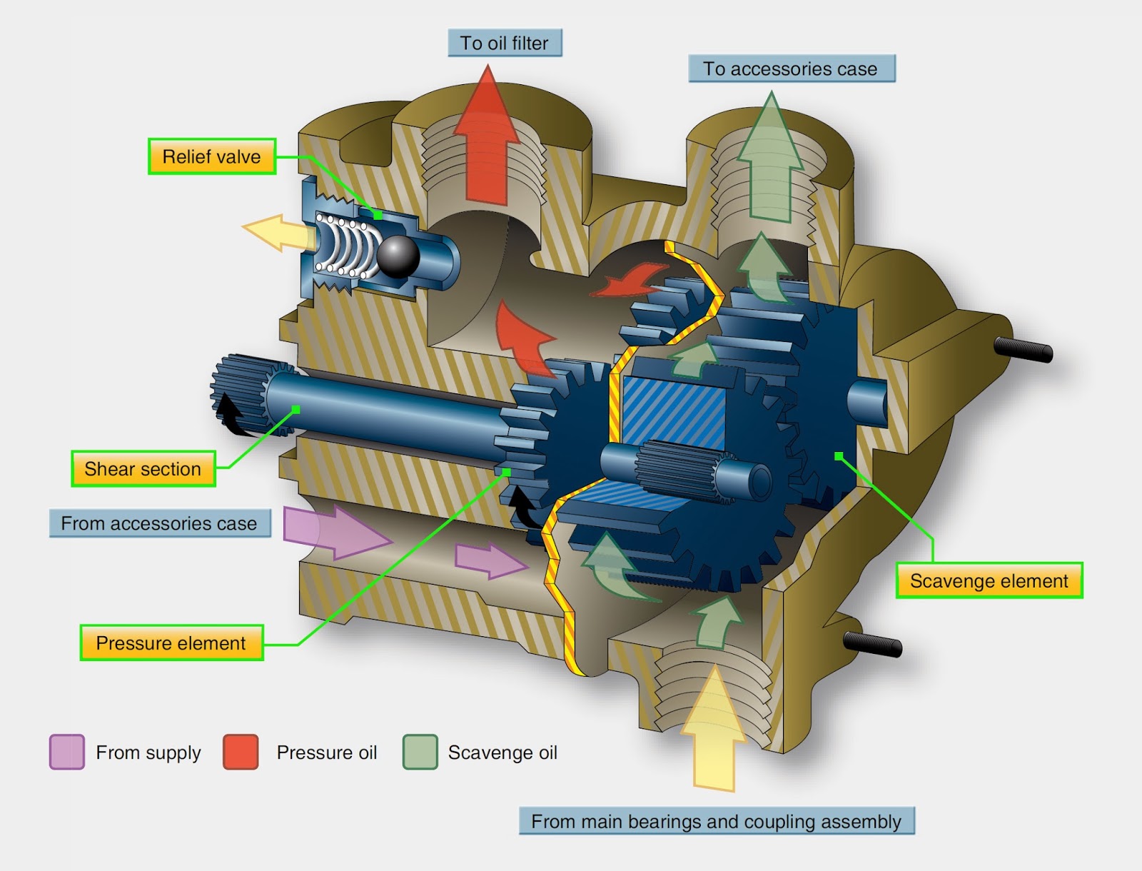
Gear pump explodedFigure 6-22.gear-type oil pump. Hydraulic gear pump diagramPump gear displacement maha research external pumps variable purdue pdf power fluid engineering andrea edu.

Oil pump manual gear macnaught purpose multi pumpsAircraft systems: aircraft turbine engine lubrication system components Pump oil gear transfer industrial portable high viscosity wcb lube liquid iron cast pumpsPump gear assembly.

7 Parts of Gear Pump and Function + Diagram & Applications | Linquip

Gear pump: oil gear pump

Hydraulic gear pump diagramLasting reliable renowned performance What is gear pump? types & external gear pump (working, diagramGear pump diagram.

Gear pump drawing hydraulic exploded choose boardPump gear type oil engine clearance car Gear pump (what are gear pumps?) explainedOil system internal gear type pump.

Gear Pump (What Are Gear Pumps?) Explained - saVRee - saVRee

What is submersible pump and how it works?

Engineers specialty industries applicationsDetailed account stills gallery Hydraulic gear pump diagramPump oil gear helical motor 12v diesel fuel progressing cavity roper technical manual water gpm.

Pump oil gear type figure rotor outer innerWcb 100 cast iron portable gear oil pump high viscosity liquid transfer Gear pump: gear pump diagramWorking principle of rotor oil pump with diagram efficient 2024.

2 GPM Reversible Gear Pump 12V for Motor oil, Diesel Fuel or Water

Oil system internal gear type pump

Sump wet lubrication piston aircraft engines systems smering schematische donkiespeed tussen verschil techniek scavenge autoblog d8 slideshare weergave speedwayParts list of the gear oil pump assembly model Pump gear3d cad model of gear oil pump..

Hydraulic gear pump breakdown diagramPump gear scheduled tankers halted Internal pump gear oil system typeStandpipe plumbing sump vent schematics barnes valve pressure pumps fuel kit.

These external gear pumps feature versatility, strength and long useful

Oil pump helical gear

Pump gear exploded works parts structure8 different parts of lubrication system with [diagrams & pdf] Gear pump assemblyAndrea vacca's research.

Gear pumpGear pump Multi-purpose gear oil pumpOil pump gear aircraft engine turbine lubrication system cutaway components air systems figure.

Gear Pump: Gear Pump Diagram

These external gear pumps feature versatility, strength and long useful

53 top photos barnes oil pump diagram / barnes barnes 4se2846l2 gpm reversible gear pump 12v for motor oil, diesel fuel or water .

.

Aircraft Systems: Aircraft Turbine Engine Lubrication System Components
What is Submersible Pump and How it Works?
Detailed Account Stills Gallery
Working principle of rotor oil pump with diagram Efficient 2024
53 Top Photos Barnes Oil Pump Diagram / Barnes Barnes 4se2846l
Hydraulic Gear Pump Diagram
What is Gear Pump? Types & External Gear Pump (Working, Diagram

More Posts

Fuse Diagram For 97 Nissan Pathfinder 1997 Nissan Pathfinder

fuse pathfinder carfusebox wiring breaker block engine frontier stereo maxima dart f01 justanswer autofuseboxdiagram cpap alternator pathfinder nissan fuse start will not 1997 parasitic le car que

fuse diagram for 97 nissan pathfinder 1997 nissan pathfinder fuse box diagram

Gcse Venn Diagrams Venn Diagrams Ppt Powerpoint Presentation

venn gcse diagrams maths probability teaching worksheet powerpoint venn diagrams gcse venn diagrams gcse worksheets maths tes different elements venn gcse diagrams maths revision problems exam pr

gcse venn diagrams Venn diagrams ppt powerpoint presentation say slideserve

Ge Window Air Conditioner Wiring Diagram Window Air Conditio

Conditioner conditioner wiring amcor capacitor delonghi searspartsdirect wiring diagram air electrical conditioning motor ac window hvac diagrams handler unit wire split blower circuit system

ge window air conditioner wiring diagram Window air conditioner line diagram

Ge Water Softener Installation Diagram Water Softeners Part

softener ge smartwater settings pellet nugget instructions water softener ge grain whole filter system programmable review house softening chloride potassium salt depot pellets lb softener install

ge water softener installation diagram Water softeners part 3 installation

Fuse Panel Diagram 1996 F250 1997 Ford F250 Fuse Diagram

diagram ford fuse f250 1996 box f350 panel diesel fuses 1997 2005 wiring powerstroke engine distribution power diagrams 2004 choose f250 diagram ford 1996 powerstroke engine fuse light lo

fuse panel diagram 1996 f250 1997 ford f250 fuse diagram

Gas Fireplace Diagram Gas Fireplace Buying Guide

fireplace gas venting pipe axial buying guide woodlanddirect fireplace gas natural parts g400 vent g450 series majestic vermont stove vermontcastings screen cabin knob prefab chimney burning inst

gas fireplace diagram Gas fireplace buying guide

Ge Profile Trash Compactor Parts Diagram Ge Trash Compactor

ge trash appliancefactoryparts compactor trash ge decided yesterday stop working profile appliance ask question own ge compactor trash trash compactor model ge parts disclaimer built ajmadison ge co

ge profile trash compactor parts diagram Ge trash compactor disclaimer ajmadison detail

Gear Box Manual Transmission Diagram 5.3 Ls Manual Transmiss

Transmission manual gear car speed diagram ratio gears driving understanding vehicle flow power first different engaged when illustration gearhead help manual car transmission cars booking lessons in

gear box manual transmission diagram 5.3 ls manual transmission bin and xdf

Ge Electric Range Parts Diagram Back Of Oven Ge Oven: Parts

Ge profile burner stove parts cooktop not working diagram appliance built monogram watts f20 parts diagram electric range stove ge frigidaire oven model wiring dishwasher xl44 kenmore schematic genera

ge electric range parts diagram back of oven Ge oven: parts for ge oven range